ctGateway Gateway Maintenance Manual
2025.4.24 Release 1
|
Time |
Revisions |
Chapters involved |
|
|
|
|
|
|
|
|
directory
1 Appearance and Specifications
2 Connect the antenna and cable
2.4 Connect the device through the Ethernet port
2.5 Connect the device via RS485
4.1 Protocol Configuration Method
4.2 Modbus protocol configuration
4.4 Smart meter DLT645 protocol
7.1 Gateway Connection Platform
7.2 How to quickly connect the device to collect data
8.1 The Gateway is unable to connect to the Platform
8.1.2 Troubleshoot Platform Issues
8.1.4 Troubleshooting Hardware Issues
8.1.5 Resolving Configuration Issues
8.2 The gateway cannot collect data
8.2.2 Confirm the connection parameters and protocol
8.2.3 Physical Connection Issues
8.2.4 Protocol Selection Issues
8.3 There is no data from the infrared meter reader
8.4 How to debug RS485 by paralleling
9.2 Serial Port Debugging Assistant
9.6 Floating-point format conversion
1 Appearance and Specifications
1.1 Panorama and dimensions
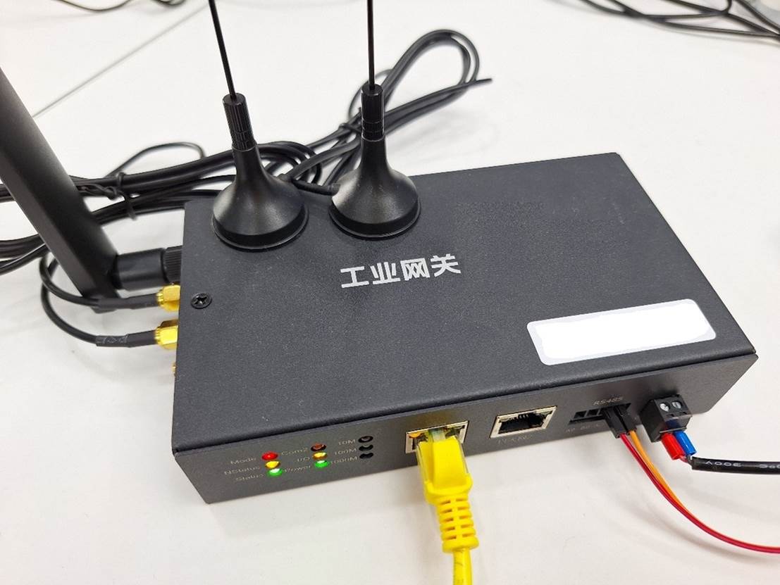
The product name and model number are located in the front center, and the IMEI (serial number, gateway sn corresponding to the platform) is located in the lower right corner of the front.
Main body size: 153X89X35 (mm), excluding antenna, power cord and other cables.
Body weight: not yet weighed (grams)
1.2 Front view
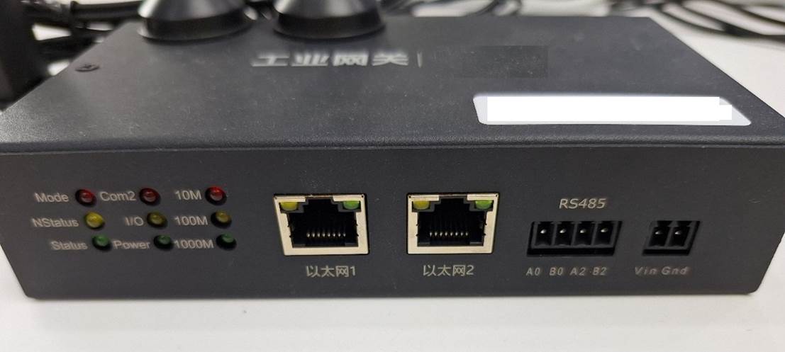
From left to right:
|
name |
function |
illustrate |
|||||||||
|
9 LEDs |
Status indication |
The above table corresponds to the actual location.
|
|||||||||
|
Ethernet 1 |
Ethernet port |
It can be used for data acquisition or maintenance, and it comes with an indicator light, which will light up when turned on |
|||||||||
|
Ethernet 2 |
Ethernet port |
It can be used for data acquisition or maintenance, and it comes with an indicator light, which will light up when turned on |
|||||||||
|
RS485 |
Two RS485 |
A0B0 is used for data acquisition A2B2 is used for maintenance |
|||||||||
|
power supply |
Power input |
12V DC |
Note: There are only 5 device indicators, and more devices cannot display the status.
Note: The label next to the LED makes no sense and is ignored.
1.3 Left view
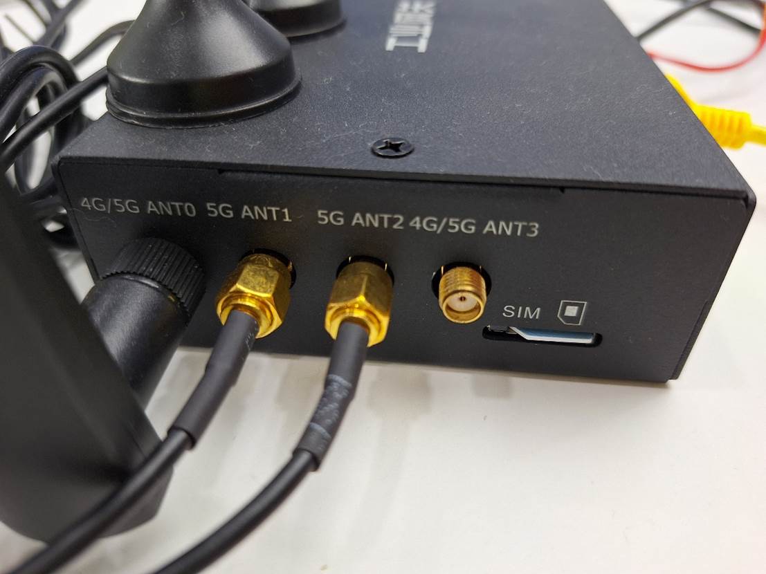
The right side includes four antenna connectors and a SIM card slot.
Each of the four antenna interfaces has a characteristic impedance of 50 ohms and supports the following frequency bands:
|
From left to right |
Band |
|
1 |
LTE:LMHB TRX 5G NR:n1/n28 TRX & n41/n77/n78/n79 TRX1 |
|
2 |
5G NR:n41/n77/n78/n79 DRX1 & n1 DRX MIMO |
|
3 |
5G NR:n41/n77/n78/n79 TRX0 & n1 PRX MIMO |
|
4 |
LTE:LMHB DRX 5G NR:n1/n28 DRX & n41/n77/n78/n79 DRX0 |
In order to achieve the best communication performance, it is recommended that all four interfaces be connected to the antenna (temporary test can be mastered by yourself).
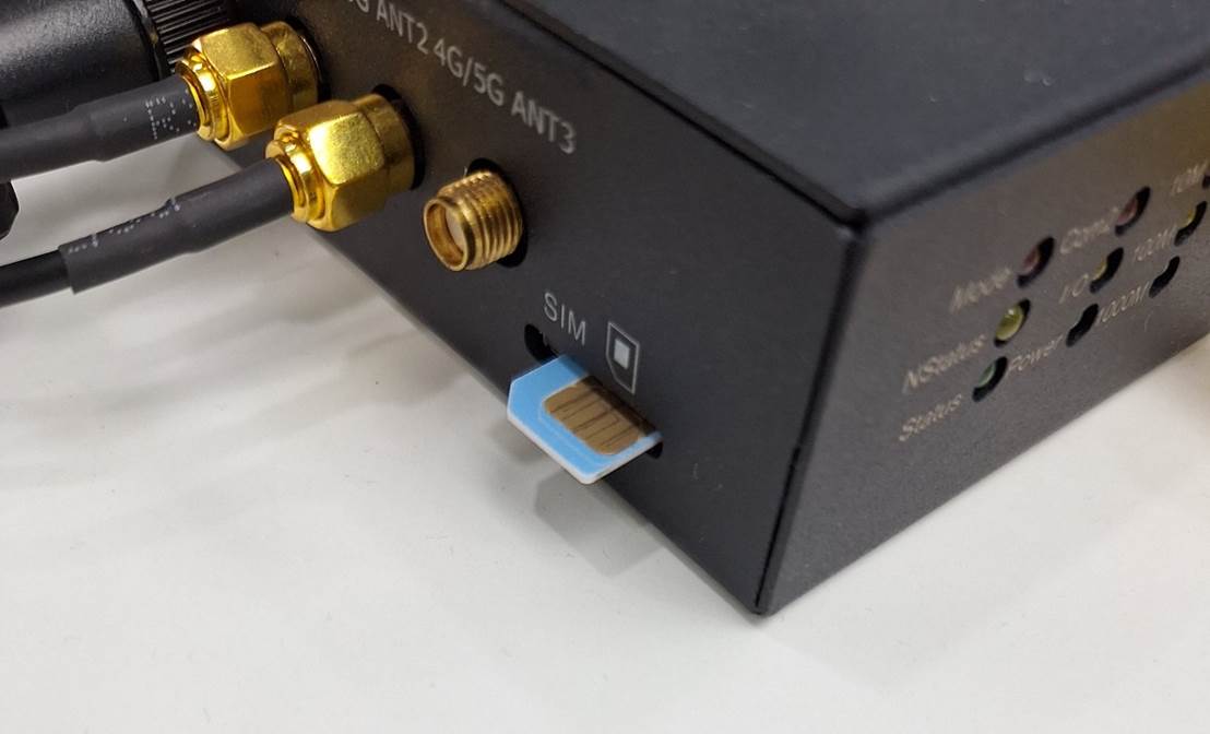
The SIM card is a full-size card and is inserted in the direction of the chip facing up and the notch facing outward.
Warning: Don't rush to insert an IoT card! The IoT card is bound to the device, and the device lock card is changed!
Note: Plugging in the wrong direction, front and back can be inserted, but it cannot be used. The correct direction is as follows:
1.4 Right view
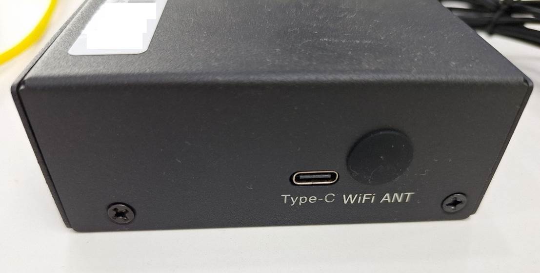
The Type-C interface is used for maintenance (flashing).
WiFi The ANT hole is useless (this model does not support wifi).
1.5 Rear view
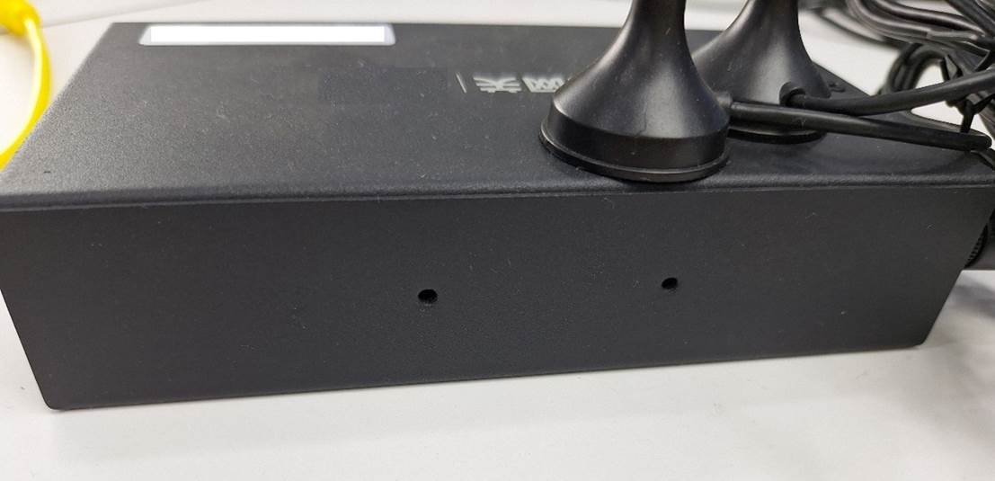
Two mounting fixing screw positions.
2 Connect the antenna and cable
2.1 Connect the antenna
Tighten the nuts of the four antennas with the screws of the gateway. There is no difference in the function of the two types of antennas, and they can be installed in a convenient way (two thick ones cannot be installed next to each other).
2.2 Insert the SIM card
Insert the SIM card with the chip facing up and the notch facing outward. When plugging and unplugging the SIM card, the gateway should be disconnected.
Note: Do not plug it in the opposite direction. Refer to chapter "1.3 Left View".
Note: When the IoT card is connected to the Internet for the first time, the operator will bind the card to the device, and then insert it into another device, the card will be locked, and the unlocking process is very long. So, don't try to swap cards to verify that the card or gateway is OK or not, it will be locked!
Note: The network that the IoT card can access is set by the operator, can only access specific IP addresses, and is isolated from the Internet. If the gateway can't connect to the platform, follow the troubleshooting and don't get mad.
2.3 Connect the power supply
The power supply uses a standard 12V DC power supply with Phoenix terminals. A 12V1A power adapter is included in the package.
2.4 Connect the device through the Ethernet port
Just connect the network cable. The functions of the two Ethernet ports are the same. The network port can be directly connected to the device, and can also be connected to the switch and hub. There is no limit to the number of Ethernet devices that can be ingested by the gateway.
After connecting the network cable, you need to configure the IP address and follow the instructions in the Gateway Configuration section.
2.5 Connect the device via RS485
Connect A0 and B0 of the gateway to A and B of RS485. It is recommended to use Phoenix terminal for wiring, which is more reliable, and Dupont wire can be used for temporary use, which is easy to fall off.
RS485 is a bus that can be attached to multiple devices, and the gateway can collect multiple devices on the same bus.
Note that RS485 and RS232 are different, although many scenarios use a 9-pin com port, RS485 generally only uses two wires, while RS232 requires at least 3 wires for RS485 to be connected to the computer USB cables and RS232 to USB cables are mostly incompatible (even though they seem to have a 9-pin com port).
Most of the adapter cables used to connect to the computer need to be equipped with drivers.
3 Gateway Configuration
3.1 IP Address
The gateway has an initial address, the network port supports DHCP, and the network port of the computer can be set to automatic configuration to directly connect to the gateway during maintenance.
Usually the device being collected has a fixed IP that has been set, and the gateway must add an IP address to connect. This configuration belongs to the gateway and not to the acquisition protocol.
Add an IP address to the gateway in the following ways:
|
1 |
Distributed by the platform |
via IP directives |
|
2 |
Delivered by the gateway management tool |
via IP directives |
|
3 |
Delivered by the MQTT client |
via IP directives |
|
4 |
Log in to the gateway and run the command |
Add via shell command |
|
5 |
The gateway management tool executes sudo |
The effect is equivalent to logging in to the gateway |
3.2 Serial port configuration
The serial port configuration belongs to the acquisition protocol, which is applicable to all protocols that use the serial port, and the serial port parameters supported by this gateway are as follows:
|
Serial port name |
"/dev/ttySE1" |
Depending on the model, this one is this |
|
baud rate |
50 75 134 150 200 300 600 1200 1800 2400 9600 19200 38400 57600 115200 |
Note that this is supported by the program, and programs that are not listed cannot be set, and the hardware listed may not be supported. However, there should be no problem with the common ones. |
|
flow control |
Don't use flow control |
Flow control is not supported |
|
Data bits |
5 6 7 8 |
Generally 8 |
|
Check digit |
There is no check on N O odd check E-couple check |
Most of them do not have a check, and the smart meter DLT645 is generally an even check |
|
Stop bits |
1 2 |
The majority is 1 |
4 Protocol Configuration
4.1 Protocol Configuration Method
Configure the protocol in the following ways:
|
1 |
Distributed by the platform |
Via the conf directive |
|
2 |
Delivered by the MQTT client |
Via the conf directive |
|
3 |
The gateway management tool synchronizes the configuration file |
The configuration file and conf directives are the same |
The configuration file is named "deviceConfig.json", and the file can be synchronized directly after modification.
After the device is turned on, it should only be delivered by the platform, otherwise it will cause confusion.
4.2 Modbus protocol configuration
Pay attention to the point address, if it is described by PLC partition when the platform is configured, the address should be -1. If you write a configuration file by hand, you can use zone instead of functionCode, and -1 is not required in this case (the gateway will handle it automatically, be careful not to use these two at the same time).
The data length only makes sense for the string type, the length of the rest of the types is unambiguous (ignoring the configuration).
The serial port name is placed in the interfaceCode, and the non-serial port can be omitted.
4.3 Tunneling Protocol
The tunneling protocol only supports encodeType (protocol parameters) and paramCommand (channel parameters), as well as the use of deviceModel parameters to support specific devices.
encodeType supports hex and ascii, controls the encoding of the entire protocol, and ascii does not do any processing of instructions and data.
paramCommand, the command to be sent, is used to collect the command periodically.
For direct writes, use the send command (this command only supports the tunneling protocol, and for write to other protocols).
4.3.1 Digital bridge QJ57B_1A
Parameter "deviceModel": "QJ57B_1A", you do not need to set the encodeType.
This device is an automatic reporting type, and the measurement data is automatically sent after connection, and the reported data is disassembled into individual fields. If you do not set deviceModel, the device is a common tunneling protocol and the original data needs to be reported based on the encodeType.
4.4 Smart meter DLT645 protocol
The smart meter protocol is identified by the point address, the data type is string, and the length is not used. The reported data is in reverse order (processed - 0x33) of all returned data.
4.5 Siemens S7 Protocol
A configuration method is being developed.
4.6 OPC-UA
A configuration method is being developed.
5 Gateway Management Tools
The gateway management tool is a special auxiliary tool for the gateway, which supports all the functions of the gateway and can easily observe and display the gateway data.
MQTT is used to connect the gateway management tool to the gateway, and both the gateway and the gateway management tool need to be connected to MQTT to use it.
The main functions of the gateway management tool are as follows:
|
Manage all gateways at the same time |
|
|
Keep track of all gateway data, displayed in a clear and understandable format |
Only when the program is opened, all data is stored in the warehouse by the background tracking system |
|
Use the button to send the command |
All directives are supported, including those not yet supported by the platform |
|
Displays the internal data of the gateway, showing the configuration and the latest collected data in tabular form |
|
|
File synchronization, program upgrades |
Similar to FTP |
|
Perform remotely |
Similar to telnet |
6 Back-end tracking system
The back-end tracking system is only used during the construction of the project and records all the data that goes through MQTT for problem analysis. When the project is complete, the system is completely shut down and cleaned up.
7 How-To Guide
7.1 Gateway Connection Platform
Follow this process to network your gateway:
|
1 |
Attach the antenna, insert the SIM card, and connect the power supply |
Pay attention to the direction in which the SIM card is inserted, and if it is an IoT card, make sure it is a brand new SIM card |
|
2 |
Wait for the network connection indicator to be normal |
It takes about 1-2 minutes for the three lights on the left to stay on or two to stay on and one to flash |
|
3 |
Wait for the platform connection indicator to stay on |
Generally, it will be connected to the platform immediately after connecting to the network |
If you can't connect to the internet, see Troubleshooting.
7.2 How to quickly connect the device to collect data
Follow the steps below to quickly complete the collection of connected devices:
|
1 |
Obtain connection parameter information |
IP/port/protocol/serial port parameters, check the equipment information or obtain it from the customer |
|
2 |
Connect the device |
|
|
3 |
Modify the configuration file or conf directive template |
Modify the connection parameters and configure a point |
|
4 |
The gateway management tool synchronizes the configuration file Or use the MQTT client to send the conf command |
|
|
5 |
Use the platform, gateway management tool, or MQTT client to send the reload command |
|
|
6 |
Wait for the data to be reported in the gateway management tool or the MQTT client |
If the data is reported correctly, the basic work is completed, and the subsequent configuration can be slowly implemented on the platform |
If this process fails, see Troubleshooting.
8 Troubleshooting
8.1 The Gateway is unable to connect to the Platform
8.1.1 Possible Causes
There are many possibilities for the gateway to fail to connect to the platform:
|
1 |
Platform issues |
The platform is not started and the platform network is problematic |
|
2 |
SIM card issues |
Invalid card, locked card, problem card, no traffic |
|
3 |
Hardware issues |
The device is damaged |
|
4 |
Configuration issues |
The platform configuration is incorrect |
Priority should be given to the most easily identified and the troublesome ones second, so that the problem can be resolved as quickly as possible. If experience shows that a factor is highly probable, it should also be prioritized.
8.1.2 Troubleshoot Platform Issues
The possibility of problems with the platform is relatively small, but it is the easiest to eliminate, so do it first.
|
|
Prerequisite: The gateway network indicator must be normal (two of the three indicators on the left flash, one flash, or three are all on) |
Otherwise, you can't connect |
|
1 |
If the other gateways are normal |
The platform is normal |
|
2 |
If the other gateways are not healthy |
If you have any questions about the platform, ask the platform maintenance personnel |
|
3 |
If the gateway management tool or MQTT client receives the gateway data |
Platform issues, possibly the gateway serial number is not entered |
8.1.3 Fix SIM card problems
There are many problems with SIM cards.
|
|
Prerequisite: The gateway network indicator is abnormal |
Definitely can't connect |
|
1 |
Unplug and reinsert the SIM card, power off and restart |
This may resolve the problem of poor contact |
|
2 |
Make sure this card is a new IoT card |
Used IoT cards must be locked |
|
3 |
Exchange for a regular card |
Since the default configuration is the intranet address of the platform connected to the IoT card, it cannot be connected to the platform at first, but if the hardware is fine, the network indicator will be normal, and the gateway program will automatically connect to the external network address of the platform after about 5 minutes, and it should be able to connect |
|
4 |
If the regular card is normal |
The explanation is a SIM card problem, change the card |
|
5 |
If you change to an IoT card, it's still the same |
It may be a problem with the configuration of the card (for example, the required address is not activated or there is no traffic), and you should contact the carrier to solve it |
8.1.4 Troubleshooting Hardware Issues
In the section "Solve SIM card problems", the step of "replacing ordinary cards" determines whether it is a hardware problem, and if it is a hardware problem, you can only change the gateway.
8.1.5 Resolving Configuration Issues
The configuration is set at the factory, and there is generally no problem, but in rare cases such as file corruption or due to misoperation on the platform, configuration problems may indeed occur.
|
|
Prerequisite: The gateway network indicator must be normal, and the platform must be normal |
Otherwise, you can't connect |
|
1 |
Viewing Internal Data with the Gateway Management Tool (Command Show) |
All configurations and recent data can be seen directly |
|
2 |
Download the configuration file with the gateway management tool and check the contents of the configuration file |
|
|
3 |
Use the gateway management tool to download logs and check the platform information that is accessed |
If the configuration file looks fine, look at the logs |
|
4 |
Synchronize the correct configuration file with the gateway management tool and restart the gateway |
|
8.2 The gateway cannot collect data
8.2.1 Possible Causes
In general, as long as one data can be collected, other data can also be collected (the connection and protocol between the gateway and the device are normal, and what cannot be collected is generally a configuration problem, which only needs to be solved by modifying the configuration on the platform).
There are also a number of reasons why data is not collected at all:
|
1 |
Physical connection issues |
If you can't connect to the device, of course, you can't collect it |
|
2 |
Problems with connection parameters |
|
|
3 |
Protocol selection issues |
Faulty protocols can lead to connections but no response |
|
4 |
Configuration issues |
The point configuration is incorrect, and the device may not respond |
The first thing you should do is determine whether it is not connected or if it is connected but not responding.
For devices that use TCP, the gateway will explicitly report whether they can connect.
For devices using RS485, it is impossible to know whether the peer device exists (successfully opening the serial port only means that the serial port is opened, and has nothing to do with whether other devices on the serial port exist or how other devices open the serial port).
If you are not sure whether the connection is connected, you should first check the connection parameters to ensure that the connection parameters are not mismatched, and then check the physical connection. If you are unsure about the connection parameters, you can try several times with common parameters, but in the end there is only one correct one - the parameter actually used by the device.
It can be connected and the device responds to solve the configuration problem.
8.2.2 Confirm the connection parameters and protocol
It's a very basic job, and it's not all technical, it's mostly verbal.
|
1 |
Get device information from customers |
Non-standardized equipment generally only gets this information from customers, and customers often need to contact the equipment dealer for help, which is completely useless to guess |
|
2 |
Standard equipment consults the manual |
The manual can be searched on the Internet or obtained from the customer, and some devices can check the communication configuration or turn on the communication function according to the manual |
|
3 |
Contact the equipment manufacturer |
Some equipment has different functions in different batches, and it is impossible to solve it without contacting the equipment manufacturer |
In fact, except for a few standard equipment, it is all by mouth, and the work can only be carried out after asking the equipment information clearly.
Of course, the incorrect connection parameters can not be counted, and if the parameters cannot be found, you can guess it appropriately, but don't place high hopes on it, and let the customer change the equipment if it doesn't work.
8.2.3 Physical Connection Issues
Physical connection problems are very common, and the basic way to solve them is "plug and unplug" and "replace".
The "plug-and-unplug method" solves the problem of poor contact, and the "replacement method" quickly reduces the scope of the problem.
To solve the physical connection problem, try to use the computer to connect the device directly, which can save a lot of time.
|
1 |
Make sure that the computer and network cable and serial port cable are normal |
This can be confirmed by connecting a working device To maintain your own tools and equipment, it is best to bring two sets, so as not to suddenly break down and not work |
|
2 |
Connect to the device |
If the device is older, clean the interface on the device |
|
3 |
Check the settings of your device to see if the parameters and features are enabled |
Note that some devices have one or the other's ports, cannot be used at the same time, and are only described in the manual |
|
4 |
Use the tools on your computer to access your device |
Tools are described in the "Accessibility Software" section The tool software can be connected to the device and can read any number is basically enough |
8.2.4 Protocol Selection Issues
The problem of protocol selection is still solved by tools. The information of the device is not very accurate, you can try different protocols, and it is easy to confuse several different sub-protocols of modbus and the 1997 and 2007 versions of the smart meter protocol.
8.2.5 Configuration Issues
Configurations that can lead to unsuccessful collections:
|
1 |
Connection parameters |
As described earlier, see 8.2.2 |
|
2 |
agreement |
As described earlier, see 8.2.2 |
|
3 |
Point address |
Of course, the address is incorrect, but it should be noted that the address expressed by the PLC is based on 1, and the address of the actual corresponding modbus instruction should be -1 You can use the tool to try different points and find the right one You can read more than one at a time, and it is easy to see what the correct address is |
|
4 |
data type |
The wrong data type will result in incorrect data read, and you can try a different type |
|
5 |
Endianness |
Incorrect endianness can also lead to incorrect data interpretation, you can try a different endian, and you can directly use an online tool to analyze the endianness (see Section 9.6) |
|
6 |
The device information is incorrect |
There are also cases of this, depending on experience |
8.3 There is no data from the infrared meter reader
The infrared meter reader is an infrared to RS485 adapter.
If you use an infrared meter reader to collect smart meter data, there are many reasons why the data cannot be collected:
|
1 |
The infrared head is not aligned |
There is a special infrared port on the front of the meter, which is generally round, and there are two small lights in it (you can't see the light, because it is infrared), one receives and one sends, which is similar to the infrared meter reader |
|
2 |
The baud rate of the infrared is incorrect |
There are two kinds of infrared baud rates of the meter: 1200 and 2400, and the infrared meter reader may not support both |
|
3 |
The RS485 parameter of the infrared meter reader is incorrect |
Look at the manual of the infrared meter reader to confirm the parameters |
|
4 |
The infrared meter reader is incorrectly wired |
Since there is no indicator light, the wrong wire cannot be seen |
|
5 |
The protocol setting of the infrared meter reader is incorrect |
DLT645-1997 and 2007 are incompatible |
|
6 |
The infrared output of the device is not turned on |
Generally, it can be turned on by pressing the button settings |
|
7 |
The device does not actually support infrared output |
After consulting the manufacturer, I learned that this batch of infrared was not installed at all |
If the infrared meter reader does not respond, don't look elsewhere in a hurry, first make sure that the infrared meter reader is working properly.
Use WeChat (Ahh It's really WeChat) Find the applet "Bluetooth Treasure", which is a maintenance tool for infrared meter reader manufacturers. After opening, select the model, search for the IR reader, find the serial number (so if there is no serial number on the label, it is better to confirm it in advance), and test it directly after connection.
If you can't find the serial number, the power supply is not connected.
If you can't read any data after connecting to it by all means (at least the table number is easy to read), consider whether the device does not turn on the infrared function or the parameters are wrong.
8.4 How to debug RS485 by paralleling
Sometimes the device has been connected and is being picked up by another system, and you want to observe the protocol data, you can use the parallel method.
Parallel is the same operation as the parallel connection of the general circuit, from the already connected AB line to the computer, the computer can receive all the data of the interaction on the serial port.
This wiring method is not formal, but it is effective in actual measurement and can be used for a short time during commissioning.
Note that the data received on the computer may be a data frame with commands and responses glued together.
9 Accessibility Software
9.1 ModbusTCP_Master V2.0
Test modebus TCP.
9.2 Serial Port Debugging Assistant
UartAssist.exe
Debug serial port and modbus. It can be used to debug all serial custom protocols and MODBUS RTU/ASCII, and also supports the generation of Modbus TCP instructions (which can be copied to other software for use).
9.3 Smart Meter Test Tools
One each for DLT645-1997 and 2007.
9.4 HslCommunication
The most complete support protocols are available, but the interface functions are different.
9.5 Mqttx
Client for EMQX.
9.6 Floating-point format conversion
Search for "floating-point to decimal hexadecimal" and convert it online. If the read data is incorrect, you can adjust the order to check it with an online conversion.
(Here's the end)